
A History of Scholarship on American Design

AUTOMOTIVE DESIGN ORAL HISTORY PROJECT
The Reminiscences of John Najjar
This is Douglas Bakken, November 10, 1981 . We are continuing the the second interview with John Najjar who retired from the Ford Motor Company, from the Design Department. The first interview had sort of taken John's life and his family--giving an overview on his early life and took design work at the Ford Motor Company up into the 1930's. One of the things that we had talked about the last time was the philosophy of design and how that has changed over the years with the Ford Motor Company. On his own, John went home and thought about this, and with the help of some documents--which we can number and identify--he has tried to sketch this out, and we are going to talk about it now, and, in a way, try, as much as we can, to pin down the styling or the design philosophy of the company and how it changed over the years, how it reacted to product changes, how it reacted to the war, and how it reacted to different people, and that's what we want to talk about today.
Q: Well, John, I wonder if we can start out and go through this, or you want to issue some kind of an opening statement?
A: No. Basically, I think it's better if we just stumble into it. I don't know if we are going to be as pure as saying "design philosophy of Ford Motor Company"--we may have to ramble a bit here. I've created these 10 or 15 sheets of paper which give an overview or a cursory look automotive design from about the 1920's to the present and a little push into the future.
Q: Okay. Why don't we just kind of call this Exhibit A, then, and then if there is any kind of shape, we can identify--we can.... Absolutely!
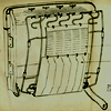
A: That's fine. ...the first sheet, and it has on it 1920, '30, '40, and '50, and after each of those 10 year periods are a side view of an automobile and a front view, and, of course, in the 1920's the Model T and its late derivatives, as far as Ford Motor was concerned, were the predominant automobile. I just put these down to refresh our memory. In the 1930's, it showed a little softer look at the vehicles. Let me jump around--this first page shows the 1920's, 1930's, 1940's and 1950's. The next page pulls it up into the '50 pluses. I should have made that '55 plus, because in '55 plus there was a significant change in design philosophy, and we'll get back to that. And, the page goes on to 1960, 1970--into the 1980's, and these are just little vignette pictures. Now, we come down to the detailed shots. On these it describes the 1920's very briefly in one-line statements. The 1920's were basically straight-line elements on the vehicles, and very few compound surfaces, and this was a part of the profession at the time--no big tools were being made to press out the sharp forms; therefore, the straight-line elements were wrapped, flat pieces of metal. The metal, of course, was thick enough so it didn't have to be stretched to take a set. As cars went on--as we will see as we go one--they used thinner and thinner metal to reduce the weight, and that metal had to be formed or curved--bowed, to give it its strength so it wouldn't "oil-can," so to speak.
Q: When we talk about metals, what was the predominant metal?
A: As far as I know, for myself, it was steel. And then, of course, casting. Ford Motor Company, throughout the years, and right up to current time, has been known for good quality of its metal in its vehicles--not necessarily sheet metal, but in the forgings in the under part where they use the brake-arms and things of that nature--they'd go to forging, whereas our competitors would use stamped steel parts, and Ford got quite a good reputation that way. The other design element that you note in this side view is that the roof profile is higher in the back than it is in the front, and this will continue on for a few years. The reasons for that, partly, was that the car, the vehicle, had wheels. It had axles on top of that, and it had a straight frame, and on top of the straight frame sat a rather high seat. Whereas the little engine was way out in front, and it was just natural to bring the windshield down. The other thing is that the engine is located just aft the front axle, in profile view, and then the radiator was a vertical line again--again this very boxy, straight-line element. And, the rear passengers on the sedan types of vehicles sat directly over the rear axle, projecting the roof up even higher. Now, looking at this basic silhouette or basic shape in front view, the vehicle was just wide enough to accommodate two passengers, and the doors came down to that frame, and then stuck on the outside of that were the front and rear fenders. There was no fixed side windows, and the spare tire was exposed. And, the headlamps and taillamps were stuck onto separate elements. Now, to me, those are design principles. They were not necessarily designed by a designer per se, but they grew.
Q: The headlamps and taillamps, they were separate because they were independent--they were hooked into the automobile?
A: That's right. They were formerly on the cowl, in further times, and these were things that you could buy separately and have them shipped in. Then we are getting to the 1930's, and the surfaces have become rounder. Instead of sharp corners, those corners turn into round--into radii, and then the use of compound surfaces increases. It's in the fenders, and into the roof, and into the hood. So, the roof profile is higher in the rear, and now what's happened is again the differential is directly underneath the rear seat passenger, and he has to get on top of that, and he is basically high. So, I asked one of my mentors at Ford when I was a young man--the clay-modeling guy by the name of Richard Benieke--I says, "Hey Dick, how come on our cars the roof is always higher in the back?" He says, "Well, that's real simple John." I said, "Why is that?" He said, "So the people in the back can look over the shoulders of the people in the front," and I don't know if that was true or not, but sounds good--all the way up in the--you know. In the 1930's the engine started to move forward. The frame started to lower a little bit between the front and rear axle. There was a desire to get the center of gravity down on the vehicle, and they were doing it a couple of ways--one was lowering the passengers, and when they lowered the passengers slightly, they had to shove the engine forward to start making room for the front feet of the passengers, and then they started to make the vehicle slightly wider, and you could squeeze in three people. But, they still came back, and they still applied the fenders into the thing. Now, they have completely enclosed the vehicle, and the spare tires were still mounted externally, and, as I have indicated here, overall height was reduced, and the length was increased somewhat. And, into the 1940's, surfaces became fully compound now, straight-line elements were becoming a thing of the past. The roof profile started to come down so it was starting to be more of a straight line. It still didn't have that racy feeling where the roof profile trails off toward the back. The wheel opening--around the wheel openings, instead of flying, fenders were now starting to become closed in, so you couldn't see all the running gear, and it also had a good purpose of covering up the mud from flying up. But, in this period the frame again was lowered between the front and rear axle, and the engine was moved further forward, making more room for the passengers to move forward, and, as a result of this, the rear seat passengers' seat could drop, which brought the roof down with it. And, now the body width is increased a little bit more, and there is ample room for three passengers. So, in this area, the windshield was angled aft with a purpose and V-ed in plain view--one was to reduce the inside reflections that you receive. When you were wearing a white shirt in the cars previous to this era, you could see your white shirt reflected in the windshield of the vehicle. It was hard to see through it. Two--and when they are starting to stamp these steel roofs now, and they are stretched all the way from the back of the car to the front, angling the windshield back at the top reduced the blank size of the sheet metal that they had to use to hit that area. So, that was another purpose. And, now the running boards are starting to be covered, or gradually reduced in width as the body got wider. In the beginning 1950's, again, we are already into fully compound surface, and the fenders now, and the body, become one. The body moves outboard to the full width, and now the fenders connected with the front door and the rear quarter panel or rear fenders connected with the rear door. So, in plain view the vehicle became one line. One-piece, curved windshields and backlights were introduced at this time in order to make the vehicle look wider and minimize the number of pieces that had to be installed. You can imagine, when you had to have the windshield in two separate pieces with a divider bar in the center, it was easier to put in the one piece. So, it became just more economical as well as looking better to do it that way. In this period, again the engine--I don't know if it was definitely moved forward any further over the front axle, but very plain it was dropped further, allowing the passengers to sink a little bit lower, bring the roof down, and now, for the first time, in the 1950's you could have the roof go from the front seat driver toward the back in any fashion that you wanted. You could have a drop-off, as smooth as you want, or you could close-couple the rear passengers to make a nice little sedan. Let's see now--the door sills now--the running boards are now gone, and you just have the scuff plates, about 2 to 3 inches wider door sills, and the headlamps and taillamps are fully integrated into the body surfaces. Again, a cost-saving factor--punch a hole in the fenders and just plunk in the light--don't have to mount them separately. Now, the '50-pluses--the '55-plus, specifically--from 1955 to, let's say, 1958 or '59. The designers--I don't know where it started--whether it started in fashion or in the automotive industry or in the aircraft industry or the introduction of a rocketry program starting up, but automobile designers started to figure that, well, fins and a lot of flying surfaces, and lines that float any place on the car was the thing to do. I think that was the period where one could say they were not automobile designers, but they were truly stylists--putting shapes on things that not always had perfect function. And, so I just put down here "extravagantly
fashioned body contours abounded, we experienced full exploration of wrap windshield." Windshields wrapped all the way around to the side. They had reverse A-pillars at the end of the windshield--made it a little hard to get into the vehicle. We had increased front and rear overhangs, increasing the length of the vehicle. Everything was exaggerated. And, the vehicles became--the name of the game became the lowest and longest and widest vehicle. So, this just simply tried to show that in a simple cartoon. In the 1960's--the public by their reaction and some of the designers and the grayer [and wiser] heads in the group prevailed and said, "Let's cut this stuff out now," and we started to get back to design for automotive beauty in itself. Simpler lines started to come in--lines that were tailored and ran from the front to the rear in a clean or singly broken line that hopped up into a modified fin. And, during this period, the vehicles went up a little bit. In fact, the overall height went up slightly to provide better room for entry and egress. We had pulled them down so far in the late 1950's that we had to go back up to make it palatable for people to now get into and [have] comfortable room in the rear seat. So--and it was during the 1960's that we started to get some super-special vehicles, like the Thunderbirds and the Corvettes before that, but we started to pick up cars for the public in the 1960's. Like the Mustang, which is one of the notable ones that came up--the Falcon was in there, and, when we got into the 1970's, there were two significant things that happened in there. Obviously, the gasoline shortage and then the Government mandates--when it was felt that the automobile industry would not introduce those things that were required soon enough, and during that period the company, even though the movement by the ecologists, let's say, happened in the late 1960's, the impact in design happened in 1970 because of the lead time it had taken.
So, what we had done was to start to reduce the size of the vehicle. Because of the enormous tooling costs, we just simply couldn't throw away all the tools that we had, all the platforms, the frames that we had, all the running gear, so it had to be done on a gradual basis, at least, as far as Ford Motor Company was concerned. So, we saw when a body or a vehicle was to have a facelift, minor modifications to it, or a complete change, at that time we would make the effort to reduce the sheet metal sizes, make the vehicles more compact. Remember, we are still talking about large vehicles at this time--six-passenger vehicles. Then, as a co-running program, we started the little vehicle programs--cookie-cutter models--they all started to look alike--the Volkswagens, the little Fiestas, all those vehicles--that went on as a separate program as a short-cut to achieve the gasoline mileage. So, we had Government mandates on safety and emissions hitting us, adding prices to the car, and in everyone of these cases, the designer was called upon there to design for function one hundred percent now, and he was happy to receive that challenge and work in that direction. And, then in this period, aerodynamic efficiencies--which were previously thought only to be effective at speeds above 55 miles an hour--were suddenly discovered to be effective around 30-35 miles an hour. So, the full use of wind tunnels was employed, and corners were rounded off in strategic places to start get aerodynamic efficiencies. In the 1980's what's happening now is that we do have an emphasis on small cars, and they are achieving the immediate fuel economies. But, being an old, gray-headed person, I still have the feeling--and that's what I am putting it down as--that the standard 6-passenger, family sedans that we are used to in America , where we have the space to do it, are going to come back. They are not going to come back in the big shapes we used to have, but they'll continue to be the smaller shapes, and the Americans will still look for the commodious feelings, and I think the Continentals, the Lincolns, the Cadillac Sevilles are echoing that--good tailored vehicles, proper size for your comfortableness. And then, coupled with this, full dynamic needs will be recognized, which will mean we may have certain air-spoilers at certain times on the roof, or we may have NASA air-scoop intakes to stop turbulence. We'll reduce the offset of the metal surfaces to the glass planes so there is less turbulence around the glass surfaces there, and then, front-wheel drive will become more predominant in order to make fuller use of the interior of the vehicle while reducing the outside of it--the outside size of the vehicle. And, what I have given here is just a brief cursory overview, and if anybody wants to go into detail on it, I can follow it up. Then, I mentioned in our last conversation that in the development of vehicles, the models of 1927 used almost as much sheet metal in covering from side to side as our cars do today, and so I have drawn on these pictures in 1927 the amount of sheet metal it took to go over the hood, down the side of the hood, down to the frame and back up around the fender on a Model T 1927 model. And, on the next page I have shown, in 1932, that that line was reduced a little bit by lowering the h d line, and then in 1940 the fender became a little easier attached to side of the hood--the side of the hood became less deep. And then, 1949, of course, it indicates that we have efficient use of the sheet metal.
Q: That's really remarkable.
A: It may not measure out 100%, but it's a concept..
Q: And, it's a pattern that you see developing that normally one wouldn't think about.
A: And if you were to project this out into the following years, that line started to grow out into contours out here in the fenders. It went through, and then they grew up in the fins, and you start to waste metal.
Well, back in that period, I was about 18 years of age, and my total thoughts weren't--since I wasn't the manager, I was a trainee learning how to do things, my job was not to take and set style at that point but to learn it and understand it, and so I didn't know, basically, the philosophy that Gregorie was shooting [for] at that time, but I was aware of it. I know we all liked the idea of trying to get vehicles lower, to try to make body surfaces fit in a little bit better, we knew the future--we thought we knew the future was to try to put headlights into fenders and ease up the surfaces, make the bumpers integral with the fenders, so they didn't just stick out there, and that occupied pretty [much] the staff before the war broke out.
Q: Well, I wonder if maybe we should go through some of the photographs I've got, that I've pulled out, as a kind of stimulus, and then we can get into some of the projects that you worked on in the war. I've got some copies of photographs that I pulled out of our photographic file, and I've got them numbered, and I thought you'd just comment or identify some of these things as you can to help us in our files here. We've got Item #1--which is #1621--can you identify this individual on here?
A: Yeah, that's John Hay.
Q: And, what does he have over on his tables?
A: Those tables are about 4 feet high, and they are modeling tables.
He is using a surface gauge to measure the height of a windshield on what appears to be a 1939 Mercury. This [one] was a 1935 Ford, and what he is working on there are quarter-scale models--one-quarter inch equals a foot. I had forgotten we used that size. And, in the foreground was this 1939 Mercury, and in the background is a blackboard drawing of a full-size automobile. John Hay is a story in himself. He came from Ohio and was quite a good craftsman, and in order to get his job with Ford Motor Company, he built a little model--a 4-door [1936 Ford] convertible model. It was about 12-13 inches long, and he made it out of tin cans, had them hammered together, soldered together, painted them. The model had full springing. The doors opened, the hood opened, the headlights lit, the taillamp lit when the tailgate opened, and he sent that in. And, when Mr. Gregorie saw that, he got Mr. Hay into our area right away. So, Mr. Hay, like the rest of us trainees, in his own profession is a superb craftsman.
Q: Did he stay in the styling/design part?
A: Yes, he retired here about 6-7 years ago--is currently living in Algonac [ Michigan ]. And, he is just a superb individual. I can't speak too highly of him. He still may have that little model. If I ever talk to him, I'll tell him to bring it down.
Q: That's a Lincoln-Zephyr--and that's photo #2--the picture was taken in June, 1938--anything that particularly stands out to you?
A: It was taken at the design building--the Triple E building, and the only thing that I am surprised about--I look at that hood side louver, that leading edge, I had forgotten they [were on] the Lincoln-Zephyr there.
Q: Photo #3 is at the bridge--you want to explain anything about this?
A: Yeah. The bridge system--Ford Motor Company was far ahead of General Motors, Chrysler, or Briggs with this particular device for aiding and abetting the creation of full-size clay models, and it was developed by Willys P. Wagner, who is now retired. Willys P. Wagner designed two longitudinal [floor] rails that sat parallel with the center line of the vehicle and ran longitudinally from front to rear. And, at each end of these, two rails were cross surface plates, so that the vehicle was completely surrounded by these metal plates. The two side plates had a little track on them--a little upstanding track. On this track rode what we called a bridge--which, in reality, was two vertical posts, one on either side of the track and a crossbeam, so if you could visualize that there's this plate on the floor, a car setting within that plate area, and this bridge straddled the vehicle. On this bridge, there are 10-inch divider bars that you can put in a measuring stick and measure from these divider bars into the clay model and orient yourself, or get any coordinate that you wanted from that particular model. The bridge had the capability of rolling on these tracks from the front edge of the vehicle to the full aft edge of the vehicle. The bridge scales could be adjusted, and on the track that set on the floor, there were holes located at every inch so that [at] every inch increment, the bridge could be locked into place. Our competitors--General Motors and Chrysler-used metal surface plates and cut out plywood or masonite templates and fitted them into the side of the clay model, and then they scraped down it. Our system was much faster for doing the original design, and, more importantly, once the design was approved, for getting off the coordinates onto the drafting paper.
Q: How many of these units might have been in operation at one time?
A: Before 1940--before 1941 we must have had about 6 or 7 of the bridges going at that time, and in the background you can see what looks like a wood structure, and that is one of my first design assignments at Ford, and that wood structure was called a viewing platform. That viewing platform was big enough to ride up over the full-size clay model so that Mr. Gregorie and others could climb up on that bridge and look down at that model to see how the line flowed in plan view from the hood to the front door, to the rear door, to the rear fender. Since Mr. Gregorie was originally a ship designer, he was especially conscious of the need for flowing lines. General Motors didn't quite go that route. They usually had a good line flowing from their rear fender to the rear door, to the front door, but then they broke in plan view, the cowl and hood line--a sharp break inboard--I don't know why they did that, but they did. This particular picture, for instance, shows a clay model inside of the bridge that you showed me. That's photo #12832, and I can leave these with you.
Q: Okay, very good. When we refer to them, we just get the [negative] number. How about this one--that's photo #4--looks like a a clay model. [Does it] ring any bells?
A: Sure does. The gentleman in the background of the model is Jay [Haskins], and I don't know his last name. He was formerly a sweeper and expressed desire to become a clay modeler, and, as is with Ford Motor Company, there is always somebody looking out for another person, and he was soon transferred and began clay modeling. Further in the background is, again, the little quarter-scale models that we worked on. Usually before you started a full-size model you developed it in the quarter-scale, and Mr. Edsel Ford, or Mr. Gregorie, or whoever was calling the shots said, "Okay, make a full size." Now what's in the bridge is a full-size model of a [ Lincoln- ] Zephyr, and it appears to be the late Zephyr--the 1939, because you can see the running board area. It may even be a study further on. It could have been a 1938 model brought in and really worked in around the doors to see if the body could be brought down flush--or the running board could be brought way inboard to eliminate any semblance of a kickout at the bottom. And, there is that platform back there.
Q: What about photo #5?
A: Can't help with it--that was one of those vehicles that was built before my time. Of course, the only thing I really loved on that was the--Whippet. [ Lincoln greyhound hood ornament]
Q: Photo #6 is a frame--rear engine.
A: No, I am not familiar with that.
Q: No. 7 is a panel delivery truck.
A: No, I had nothing to do with the design of that. I remember doing some schematic drawings which indicated the colors and how to assemble the front end of that which we made up in the design department and sent down to Rouge.
Q: No. 8 is from August, 1937--a cab-over truck.
A: I didn't do any designing on that, but that was in there when I-Just about the time I walked in the door, so it was there. I probably had nothing to do with it.
Q: No. 10 is a Zephyr, has the running board.
A: No. The picture was taken before I got there. I don't know what they would have been exploring. I am not sure. I notice back here--this quarter window has what looks like a CV--controlled ventilation--but I am not....
Q: No. 11--we have looked at this before--the possibility of it being an English car.
A: Yeah. About that time, war clouds were gathering over in Europe ,and a fellow by the name of V.Y. Tallberg--I think it was Germany . Somewhere between 1937-1939--I am not sure--there was a liaison between design need for the German [Ford] cars, and they'd ship some of the cars over, and we'd work on the front end of the model, and I don't know whether I worked on this one or another one, but several of us had. About 3 or 4 front ends [were] being done simultaneously, and each one of us had a front end to do. This looks like it could have been one of them. Although, by the date on this, that would have been December, 1937. I would be only in the design department for a couple, three months at the most. I would not have had an assignment like that.
Q: No. 12 is an experimental car.
A: I have no idea. In fact, I am surprised. I didn't know Ford Motor ever did anything like that.
Q: Well, it may have been just something that--a small model. It looks like a 1/10th size.
A: I know that Mr. E.T. Gregorie did a number of roadsters for Edsel prior to the time the department was formed, and at that. time keeping the wheels separate from the body, doing a little race car, and then enclosing them was prevalent--sort of like this rear cover.
Q: No. 13 is the next photo showing a mockup of the seat and the door. I guess my concern here is, is this the way that it was done? What was this called?
A: Well, it wouldn't be called a seating-buck, obviously, and I don't know what [term] we used then, but that's the way they were shown. The door panels were usually set up on easels or wood forms and set alongside of the--either the front or rear seat, which was trimmed in the proposed design. So, you could say it was an interior platform mockup.
Q: We have a couple photos, I guess, that are related-.-gentleman working in a studio--#14 and #21--and, you've got #13766.
A: I put down--as I wrote on mine, "Designer Bruno Kolt sketching for Design Department, circa, 1939." In the background is a. 1939 Ford, a wooden mobile viewing platform, boards for displaying drawings and a portion of a clay modeling bridge. The wooden mobile platform was used to look down on the top view of the clay models to ensure the cars contour line flows smoothly--for example, the hood, the doors and the roof quarter panel.
Q: And, he was with the [styling] department.
A: Prior to the war years, and his particular forte was doing grilles-the front ends of the vehicles.
Q: What about photo #15?
A: Yes. That brings back good memories for me because I have other photographs to go with it. Your photographs shows John Najjar, in a smock, working on a full-size blackboard drawing. We called the big boards that held the full-size drawings of automobiles, blackboards. The reason that we had them painted black was that the black allowed you to put renderings on top of that board, and the black would recede into the background. This blackboard would be anywhere from 17 feet to 24 feet, and at each end were mounted, supporting wheels which were spread out, of course, so the blackboard could be used on both sides. The blackboard, being about 71 feet high, and could be used on both sides, and was faced with plywood. In this particular drawing, the man on the right is Edward A. Martin, and what we are doing here is making a layout on what appears to be a full-size, 1939 Mercury.
Q: Off to the left is some device that has my curiosity.
A: Yes, that's called a "sweep-rack" and had wheels on the bottom of it, and it [was] set up like a mobile clothes-hanger rack, and hanging from this rack on either side are long, wooden splines--these splines were about 40 inches in length, and we called them sweeps or splines. Spline, of course, was a one-by-one piece of wood, 4 feet long to 10-15 feet long, and you could bend these pieces of wood to take on a smooth curve. The sweeps were irregular shapes, about 2-3 feet; long, keeping gentle curves on them for--people referred to them as French curves in the drafting business--for drawing the lines on the models. And, then there are the true sweeps, and the true sweeps, again, are 40-42 inches long, and they are segments of a radius, and you'd get a 40-inch radius, 50-inch radius, and it would be set up in a series of coverage. We'd use these full-size pieces, usually made out of wood or plastic, or aluminum, to draw.
Q: This kind of relates to a photo you have. I am just wondering if there is a number on the back of this one.
A: The photo that I have is a blackboard drawing being colored in. After a drawing was done on tracing paper, it would be run off on the blueprint machine, brought back, and stapled up to the blackboard, and then the designers would take chalk, large chalk sticks, and color in the salient feature, and people--passengers that would be in the vehicle-this would be shown along to management, showing how much room there would be for the people. In the drawing that I have, the man in the foreground is Tucker Madawick, who later became President of Design for RCA Corporation. The middle man was Edward A. Martin, who was my mentor and teacher, and then, of course, myself, John Najjar. And that's the drawing.
Q: That's the completed drawing, and that's #16147. The next one that I have is #16. I don't know how you would describe it.
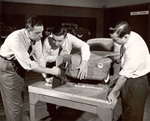
A: Well, that's an action photograph of clay modelers at work, loading the clay onto a clay model. Loading the clay meant the raw armature was rolled into this bridge form, set into position with its jacks and locating pins, and the clay ovens would be heated up to a temperature of 140 degrees. Chavant clay was used at that time, and usually came in either a gray-green color, or a rust, chocolate color. Ford Motor, at that time, was using the gray-green Chavant clay, and this came in billets of about 10-15 pounds apiece. These were put into our warming ovens, which at that time--and I have a picture of them back in my book here--were simply boxes with either lightbulbs or heat element strips, and you had to watch the clay very carefully because once the clay got too hot, it turned liquid, and then the sulfur broke out of it, and it became useless. But, when the temperature was just right, it was completely malleable in your hand like bread dough just before you bake it, and with this in your hand, you could now start to apply the clay to the clay model by putting it on in thin layers, layer after layer after layer. And, after a certain time, your hands toughened up to the heated clay, and the friction of applying it, and you soon found out your ability as an armature designer was to be able to foresee how far [thick] the final clay would be. You'd sometimes get clay 6 inches to 8 inches, to 9 inches deep on a model as it went from rough clay to finish. So, what these gentlemen in this picture are doing (and, they're all over the model)--Bob Paulson is the man with the striped shirt on the left. That's the only one I can identify--(I've got another photograph that shows that Jimmie Mearns is somewhere around that model). They are putting in the rough clay, and those are hand marks on there rather than tool marks, and the grooves you see on the surface are--there's hot clay in your hand, the fingers rubbing it off.
Q: Is it possible to estimate how many people may have worked on this and how long it took them to reach this stage?
A: Yes, it is, and it varies. One is your time element--if you have to make ready for a show, you can pour so many more man hours on it. If you have a lot of leisurely time, and the drawings aren't quite done, it'd take longer. But, usually when we were loading the clay on--loading the clay on was the task of about six people, and it was a rotating thing because it was an ugly job, and so you take a crew of six guys off of one clay model: "Okay, it's your turn to load the clay on this," [and] so it rotates. So, there'd be--the front of the vehicle would take two guys, body would take two guys, and about two guys on the rear was the way we worked it. As we got more sophisticated, we stopped claying in the windshield, as I notice on the model--we tried to cut in. The model shows the way as we got more sophisticated--we cut out wooden templates of masonite and sank them into the surface (since they are flat planes) and brought the clay up to the glass planes. Time element on this--the armature would have taken about, oh, a week and a half to two weeks to build. It was made out of wood and hung on either to a metal production frame, it being its underlayment, or there'd be wood--two-by-twelves-that would be the frame to which the armature would be built. So, that took about a week and a half to two weeks. Loading the clay on would take about a week--loading the clay on was just not simply making a blob of clay, it is building the clay up to predetermined surfaces, usually set in with templates or some other points from our bridge, and from that point on, after you had it loaded and, in general, roughed in, it would take you about 8-12 weeks to finish up that clay model so that it was ready for paint, or shown in its final clay surface, smoothed down with turpentine and silver foil on the moulding and door handles, and the bumpers rolled up. So, elapsed time--let's say 6 to 8 weeks--about 3 months.
Q: No. 17--how can we describe this?
A: That is an armature that is being torn apart. It was, obviously, a clay model at one time, and it looks like circa 1939 because of that shape on that front. It was either a Ford or a Mercury, and it has been through the shows, and it's no longer needed, so the clay is being stripped off it to be used--put into the machines and rebuilt again. The wood armature could again be used if they found out that they could rip off the back end and add new pieces of wood to conform to our new shapes.
Q: Who would have constructed this armature?
A: Our wood shop. That was under the aegis of Jimmy Lunch, who was in charge of our metal/wood shops. In the wood shop there were about 10-12 people in there--pattern makers, and Johnny Hay was now in there--the man I mentioned previously.
Q: Did this wood have to be of any particular type, or did it...?
A: [laughs] I am glad you brought that up--no, it didn't. As far as I am concerned, it could have been just straight wood, lathe work, or knotted--but not at Ford Motor Company! They had a habit of ordering in No. 1 clear, and that meant no knots in the wood, and all the wood that went underneath in the bulkheads of this was pure, so when they broke up one of these models, and they went to truck the wood out, it broke your heart because you'd just love to have the piece of wood for whittling. So, that's just a point.
Q: Interesting. No. 18, I think, we looked at before.
A: That's a full-size, blackboard drawing of a 1939 Mercury, and it shows all of the important look of the vehicle. Now, from this drawing, it could be just shown as a mechanical drawing, or we could color it in to make a full-size, color drawing, but it showed the significant outline of the vehicle, its stance, how the bumpers were attached, the fender profiles, the hood profile, the door openings, and then inboard, and hidden lines--the seat movement, the steering wheel, the floor of the driveline--a pretty complete informational drawing.
Q: No. 13763. It's kind of interesting. We each have the same photo.
A: It's a birdseye view looking down at designers, clay modelers working on a full-size clay model. And, you can see the bridge platform, that I previously described, and the bridge itself. There are four men working on this particular model, and the man with his back to us with the apron on and his foot up on it is Jimmie Mearns, who was a wood pattern maker. I think the man with his back to us was another wood maker by the name of Tony Schuck. The man facing us, on the far side of the clay model, again in the striped shirt, is Bob Paulson, and I don't know the name of the gentleman on the far left. Jimmie Mearns is standing on a step-stool. The step-stool was designed to have four legs to come down, and it would bridge over the rails, so you could climb up on the vehicle and apply clay to the roof, and he is standing on a piece of 18x24 cardboard on which they would lay their tools--scraping tools and blue steels--so they didn't get embedded in the clay, and so they kept their foot print also off the clay model.
Q: What are they working on? What is the product?
A: That's a good question. It's hard to tell. But, the way the back of that roof is, it looks like it could have been a couple--starting off with a coupe, and the way the fenders are starting, there still is a remnant of a running board coming into it, so I'd say circa, 1939.
Q: What about in the background? Can you identify anything in there?
A: A small blackboard. You can see the edge of it, and in my photograph on the right you can see some layout tables, and in the far background are the designers' drawing tables. I am trying to identify the car. That looks like a 1938 Ford to me--looking at this line and the way the fender is.
Q: Photograph #20--where we have several individuals looking at a car--I guess you've got a #13764. Can we identify them?
A: The man on the left, I don't know. The man with his hand on his hips is Bruno Kolt, the man we saw in the previous sketches. The man on the far side of the vehicle, facing us, is Frank Francis. He was secretary, clerk, bookkeeper to E. T. Gregorie. Then, the next man, with his arms folded, is John Walter. He had charge of instrument panels. And, the man on the right was Walter Kruke, who was in charge of the interior-the fabric and the seat trim styles. Looks like they are looking at a 1939 Mercury--one of the first models to be delivered.
Q: I guess this would be in a certain [outside] area--showing area or what?
A: It was outside the design department in the open area. The design
department is on the South side of the Tripe E building. There is a [space] that was clear all the way up to the administration portion of the building, and in that area they would bring out some of the cars. If it was a production car, they probably wouldn't have tried to have any secrecy.
Q: And, that is #22. We looked at this before.
A: The only thing different about this one is--on the right-hand side of it is a portable drawing table, on top of which are some sweeps that were used in doing further drawing you notice, on this particular blackboard. It, obviously, was a blueprint of a drawing, stapled up upon a white background, and then the windows were cut out, so you could fully see the silhouette of the vehicle.
Q: To identify those--that was good. Gave us a lot of useful information.
A: You are welcome to take these--trying to find Life magazine that had this shot in it--which seems to be better than any of the shots we have looked at for showing the scope of the design department--this was 1940, Life magazine.
Q: We call this [photo] #23. This would have been in the Triple E building?
A: Yes. [I'm] sorry, I tore it out of there... but it was a wholearticle on Ford Motor Company in Life, and I don't know what time it was--1940. I'm starting to go through the book stores, and I am sure I can find it. But, this shows the picture of one quarter of the design department--one quarter or one half--looking toward Oakwood Boulevard-out over the ponds. So, on the right up here would be the administration portion of the building--the [Henry Ford] Museum was over here--there would be a wall coming across here to separate us from the other people.
Q: One thing I noticed in this photo, I am a little concerned with all the windows there. Were people able to look in on the work that was going on?
A: Oh, no. At that time we were in the country--everything across Oakwood Boulevard was field except for a gas station, and there was a little guard shack just as you turned in from Oakwood Boulevard onto this--I don't want to say Brady--into the Ford area, there was a guard shack--so people were shunted down along the road. I think you can see it from this photograph, down to the front of the building. But, there were also bushes. So, where we can see out to the road, when you were walking along there, you couldn't see in. You can see the two types of [styling] bridges here. This was one type of bridge we had, and then we were told that the bridges were twisting--that structurally they weren't strong, so "bird-cages" were built on top, and they still weren't strong enough, so we went back and tried another one. This bridge was made out of plywood sheathed with 1/8 inch aluminum, and then boxed, and it was a dodo--it did fine, but it wasn't a sweetheart. It was just about as effective as the original one. But, I particularly like this photograph because it shows all phases. It shows a little mockup showing the seat and the profile of a roof as it came forward with the steering wheel mockup in it--showed me with a full head of hair working on the model--E.T. Gregorie--showed the sweeps laying on the table--the sweep rack.
Q: Shows some of the projects that were going on at that time.
A: You want me to turn this whole book over to you so you can take out what you want and--this one I'd like to know if you keep any of the material on it--just for my record. You'll eventually get it all, anyhow.
Q: I wonder if we should talk a little about some specific projects and get into the war, too, a bit here. One of the things you had listed on your list of projects were the 1939 Ford--and also the first plastic car. I am wondering for a place to start on any of these projects--where we should pick up again on the late 1930's discussion. Is there a convenience place we can pick up on some of the work you did at this time?
A: Well, during that time, it was a question of personal growth, as an individual learning the tools of my trade, going to night school, so I was doing that. And, as I got better at my own abilities, I was assigned a greater degree of tasks, and one of those tasks turned out to be on the first plastic car. Edward Martin and I were assigned to work on that vehicle, and E.T. Gregorie, being the type of person he was, when he took on an assignment, he wanted to do the whole thing, so we had a carte blanche order to go out and do it. So, we boldly set up the engine, and the frame, and the springing, and the structure that goes through the Apillars and B-pillars, and proceeded to build a small model on it. As I mentioned in our last session, Mr. [Robert] Boyer, who was assigned to do the plastic work out of soybeans by Mr. Henry Ford, had his own ideas on it. If we made it out of plastic, nobody else was going to get the credit, he was. So, somewhere along the line, we were taken off the program, but that was a memorable program for me because E.T. Gregorie fed us the information he wanted, and we did the detailed drawing on it, sent out to have the parts made. It was always a thrill at that time to see the parts come back, assemble them and see how they worked.
Q: When you say the parts came back, was this sent to some jobber?
A: The tubular frame was sent to our shop--the parts would be sent toour shop. If they didn't have the facilities to do it, they might go out and have it done by a jobber, but most of it was done internally. And, the parts I refer to, of course, were for this little, 1/4 or 3/8 scale model. And, one of the things of personal interest was that Mr. Gregorie could hardly wait for the model to come back of the body frame. If you can visualize, the plastic at that time wasn't going to be welded into itself by plastic glue. As I remember, it had to be attached to an armature, or a structure, and so it was this structure that Mr. Gregorie had conceived of that was brought back. One day we sat it on the floor, and proceeded to jump on it to see if it would break, and this was his method of approving that it would be structurally strong when it was full size. So, it was just a point. The next thing I had an opportunity to do was working on the Continental--the first Lincoln Continental for Mr. Edsel Ford--and that was quite challenging, and being able to model the shapes onto the deck where I worked--on the deck of the spare tire, and the rear fender, and I was doing that work for Bill Wagner at the time, and I was able at that time to influence the shape of the surfaces. I was told what to do, but I still was the one who had to flow the surface through, and I am not saying I got it through the first time. Mr. Gregorie would come by, say, "No, John, that's a little too sharp. Do it this way." So, in his mind, he designed it, but by my 18-year-old-19-year-old mind, I designed it, you know. So, that's about all I can say during that period of those vehicles. One element I had forgotten--I think it was in this period before the war started, I was also assigned to work on the Ford Ferguson tractor. Harry Ferguson and Henry Ford had struck an agreement to build the first non-tiltable, or-rearable tractor. When he rolled this tractor into our place, I remember one of our clay modelers--his name was Bert Pugh--again, he was a sweeper who had been given a chance, and it was his job to work with me. We clay modeled the sheet metal on the front end of this tractor, showing the hood and grille work, and, I think, I have a couple of design sketches of that at home. But, the important thing I am trying to get at was that we finished this model, rolled it out and set it out in the middle of the room where it was, cleaned everything around it, and then we were relegated to the side as Mr. Gregorie made the presentation. I don't remember whether Edsel Ford was there, but Mr. Ford and Ferguson came. Mr. E. T. Gregorie made the presentation, we kept looking from around the blackboard, and Mr. Ferguson walked up to the model, onto the left hand side of it, and he put his foot onto the clay step, and went right through it. Mr. Ford laughed, and then he patted Ferguson on the back, and Mr. Gregorie was apologetic, and then he walked around to the right side of the model, after a while, and Mr. Ford took a pencil out of his pocket and did something to that running board, and they left. Photographers came around and took pictures. I walked up to the model and on the running board. I said, if my memory is right, "Okay, H.F." Now, shoot forward to circa, 1955, no, it was about 1952-'53. Ferguson is suing Ford [1948-1952], and they are trying to find out--I remember the legal office came down and asked if anybody is around who was around at that time, and I identified the photograph. Whose signature is that? "Okay, H.F."--okay, Harry Ferguson, or Henry Ford." and, I said, "Mr. Ford," and they told me that I would probably be called for a deposition, but I never was. I am sorry--that was a just a little anecdote.
Q: Interesting. You had mentioned, too, that you were going to school. What did this constitute, and where was it?
A: There were three places-- Meinzinger Art School was on the corner of Woodward and Warren. I don't remember the man himself, but he had a commercial art school, and one of the things he taught was air-brushing-applying a paint through a spray gun powered by air, and I wanted to learn this skill, because I had the feeling it was going to be the next wave in rendering. I think I saw G.M. had some already, and I thought I better learn it. So, I went down there to learn the commercial techniques. And, I was going out to Cranbrook , took a couple other classes. They had some sketch classes going out there, free life--and Wayne State had some commercial courses in doing advertising work. At that time I was still a young man, and I wasn't sure I was going to be in automotive design all my life, and I was preparing.
Q: Would there have been any other employees that would do the same type of thing that you did?
A: Yes. Take Bud Adams, a friend of mine then and still is today, he was going to LIT--Lawrence Institute of Technology--and night school, and he was studying. He didn't want to be a designer. He wanted to be an engineer. He did become that--an all-A student. I don't know of any of the other fellows that went out to school at night. They sure must have. But, I know a couple of them--like the rest of us--would go back to the apprentice school and take some of the mathematical courses, and I kept that up all during my early years. But, at that time there was no formal school that we could go to. There was one just starting about that time out in Los Angeles -- Los Angeles Art Center --started by "Tink" Adams-quite well known in the business now, and sponsored by Ford Motor, General Motors and Chrysler. But, there just wasn't that kind of thing. You had to go to different places, plus your natural talents.
Q: Well, we wanted to talk about some of the war projects that you were assigned. Can you refresh us in what happened when the war broke out?
A: Okay. That was December, 1941-- Pearl Harbor and just before Pearl Harbor . I don't know why it was--sometime around in October, as I remember it, we were told we were going to do drawings of the B24 bomber -- that the design department was going to convert to war. And, at that time, Johnny Walter, who had charge of instrument panels, quit. He figured he could still get work on the outside. He wasn't going to be transferred over to the airframe building and become a detailer. Certain fellows were told at that time they would be transferred out. The rest of us, until their time of transfer, were put on the [drafting] board, tracing down the Consolidated B24 bomber drawings--tracing them line for line and putting Ford Motor Company title blocks on. So, it became our drawings, with our numbering system. They had the contract, and they were going to get running. So, they had their own discipline. So, that's what we were doing at the design department, starting there. Then, I received my orders from the design department to go down to the Rouge plant and work on the M4A3 tank. I reported to the man there by the name of Dale Roeder. I remember meeting Dale. He had a little cyst on the top of his balding head, looked like the turret of a--he was kind of disgruntled that he was receiving a stylist, as we were called, and what the hell do you do with him and all that stuff. He sent me out on the board to work for a man by the name of Stan Vahey--big red-headed Irishman--big bold hands that seemed so crude until he picked up a pencil, and they became very delicate. Now, Mr. Vahey sat down, had a talk with me, asked me what experience I had and told me what I needed, and he said, "You will be doing--you will be working on production illustrations, but if you want to do meaningful work, John, I advise you to take trig, algebra, and these other things." So, okay, I was classified a 2F because I had a war job at that time, and I signed up for all the classes YOU could think of and worked 10 hours a day, and then go to these classes at the Rouge plant afterward, and then go home after that.
Q: Were these sponsored by the company?
A: Yes--very much so.
Q: Was it part of the Henry Ford Trade School , or...?
A: I think it was over at the Trade School because I remember going over--the hospital was underneath, and I went upstairs to the classes there. And, I did production illustration, and working down at production illustration there was another man there--a young fellow by the name of Arthur Querfeld--whose family owned the Querfeld Funeral Home on Oakwood Boulevard, and Art was never in the design department, but he was down there doing production illustration, and he was doing production illustrations of some of the armored vehicles. I was doing production illustration of all the--for the instruction book for the M4A3 tank--this is the way you throw a "tarp" [tarpaulin] on, this is the way you install a heater, this is the way you tie down this--and I always loved the way Art drew tire. He got the treads in it very nice. Now, I just knew Art casually then, and I got to know him better over the years.
Q: When we say "production illustrations"...?
A: A production illustration is a hand-drawn, photographic visualization of an item, so that if we had designed a Tarpaulin, say--let's say we had designed a metal box to fit into a certain part of a tank, it might be two months before that metal box got into a tank to take a photograph of it. It was important that you had a picture of how that box fit on there so it was a pictorial illustration--a photographic type of art rendering of installations. At that time, Mr. Vahey had indicated that there was a competition on between Chrysler--no, between Fisher Body, who had the M4A2 tank, I think it was, and we had the M4A3. They were the same tank, but G.M. was doing one version, and we were doing the other, and there was a competition on to show the drawings of the tank to the top brass, whoever that was, and I was given the assignment to take that M4A3 tank and do large, mechanical drawings--scale drawings--of that tank and dissect it. I took the tank and cut it longitudinally in half, and showed its innards, right through the engine, the drive lines and gun-sights, everything, and I did it all in ink, and it was done on a sheet of paper 24x36 [inches]--that was Drawing V. Then, I did a side view of the tank, as though you'd see it from the side--a front view, a side view, and a top view. These drawings were taken to Washington , the presentation was made, and later it came back, if I remember right, and they congratulated Stan Vehey and me personally because the Ford drawings looked the best. So, I was quite proud. But, by that time, Mr. Vahey and Mr. Roeder had confidence that I could do something else, and they put me in charge of scarfing--scarfing was taking a large slab of armor plate steel--a plate 3 feet wide, 21 inches thick, 17 feet long--and that piece of plate had to be cut out by the torches, with the proper angles on it, so when it was done--like one side of a house--it would fit on either one side of the tank. And, in order to get those planes right, you had to know your trade, you had to know your geometry, and have your measurements right. Of course, Mr. Vahey was there to check me out. I was proud to say I was in charge of the scarfing for the sheet metal of the hull and also had another competition they assigned me to, which was to design the air intake grilles on the back of the tank that would allow air to come in but no bullets. And, again, it was a competition. Well, this one we lost--I lost. The one that won was a Venturi type of van done by General Motors, and I had done one that looked like a--the letter S that interlocked--but they felt one that they didn't have to move (actuate) was the better one.
Q: When you were working on these projects, would you actually have the tanks there so you could see them, or...?
A: Yeah, we were upstairs, at Gate 4 [Rouge plant]--seems like I always made a circle again back to Gate 4. We were above where the old apprentice school was, and where I was assigned to the first time by Mr. Ford when I left the apprentice school. Back up to that area, that had grown in size now--across the street from Gate 4, was the engine building, and we had what we called the White House, and in the White House were samples of the jeeps, samples of the tanks, samples of the gun carriers. then, to the one side of it, they had a garage where they assembled all this stuff, and then they had a test driver go out and test it--a guy by the name of "Speedy" something was our tester. And, in that area, Mr. Vahey said, "Okay, John, we are going to try you out. You are going to do the fuel-line installation on this M4A3 tank. We want to make modifications. So, design it, we'll approve it, and you follow it all the way through to all your drawings, and if the parts are made up, install it and test it. And, so that was the last thing I did before I went down again to the draft board, and they decided I was a 4F (draft classification)--they wouldn't take me. I had a physical problem--still have--and the Ford Motor Company heard I was 4F--I was taken out of there and moved back to the design department to work on the last vestiges of doing cars again and beginning of the new cycle--they were allowed to do just a little bit.
Q: So, roughly how long were you working on these so-called war projects?
A: Let's see. I went there January, 1942, and left there November, 1943, so that would have been a year and three-quarters. A long stretch.
Q: What about your work schedule during that time? Was it from 8:00 to 5:00 , or was it much longer?
A: Much longer than that. It was a 10-hour day, and overtime on top of that on special things, and a 6-day week. And, I lived out on the East Side near the City Airport , and at that time we had OPA, and you had to get the fuel rationing, and I picked up people all the way across the city to do it. And, as things--the Summer of 1943, as an aside--I was a young man, and there were a lot of females around, and I didn't know how to dance. I [answered] an ad from Arthur Murray's. It said, "You [don't] need to [know how to] dance. We need instructors, come down." So, I applied there. You can imagine, after working 10 hours a day, and doing some studying, I'd get down to the Statler Hotel, they accepted me, and I was taught how to be an instructor, and I'd get down there, maybe about 8:00 o'clock and after about 4-5 weeks, I knew how to dance--how to do the basic steps, and they put me on the assignment of dancing with the women who wanted to buy lessons. I got tired of the selling bit, and they suddenly farmed me out to the YWCA's, and I had the downtown YWCA--must have been 35 women, and there must have been about 6 men--and I remember putting on a demonstration down there where we had the sounds of the Battle of Britain, and we had search lights throwing aircraft shadows on the ceiling, and we invited servicemen to come in to be taught how to do the dances. And, I was the instructor. So, I did that for about two years.
Q: Well, I think we've taken it up to the--to after the war. It would probably be a good time to end the second one. We can pick up from postwar on in the next session. Thank you.
<<Previous Section - Next Section>>
About the Project | Credits | Contact Us | Student & Teacher Resources | Site Map
©2004-2010 Automobile in American Life and Society